Prerequisites
- Hardware:
- 2 x STM32F103C8T6 (Blue Pill) boards
- 2 x NRF24L01+ PA + LNA modules (with external antenna for extended range)
- 2x AMS1117 3.3V voltage regulators (to power NRF24L01 modules)
- Capacitors (10µF to 100µF) for power stability
- 2x Joysticks (for 4 channels: X and Y axes of two joysticks)
- 2x Potentiometers or switches (for 2 additional channels)
- Jumper wires, breadboards, or custom PCBs
- FTDI programmer or ST-Link for uploading code to STM32
- Software:
- Arduino IDE with STM32 support (install the STM32 core via Boards Manager, search for “STM32F1xx/GD32F1xx”)
- RF24 library by TMRh20 (install via Arduino IDE Library Manager)
- SPI library (included with Arduino IDE)
Hardware Connections
The NRF24L01+ PA + LNA module uses SPI communication and requires a stable 3.3V power supply. The STM32F103C8T6 operates at 3.3V or 5V, but the NRF24L01 requires 3.3V. Use a voltage regulator and capacitors to ensure stable power.
Pin Connections for Both Transmitter and Receiver
| NRF24L01 Pin | STM32F103C8T6 Pin | Description |
|---|---|---|
| VCC | 3.3V (via AMS1117) | 3.3V Power |
| GND | GND | Ground |
| CE | PB0 | Chip Enable |
| CSN | PA4 | Chip Select |
| SCK | PA5 | SPI Clock |
| MOSI | PA7 | SPI MOSI |
| MISO | PA6 | SPI MISO |
Additional Connections for Transmitter
- Joystick 1: X-axis to PA0 (analog), Y-axis to PA1 (analog)
- Joystick 2: X-axis to PA2 (analog), Y-axis to PA3 (analog)
- Switch 1: PB1 (digital input with pull-up)
- Switch 2: PB10 (digital input with pull-up)
Additional Connections for Receiver
- Servo Outputs: Connect to PWM-capable pins (e.g., PB6, PB7, PB8, PB9, PB10, PB11) for 6 channels.
- Alternatively, use a PPM output on a single pin (e.g., PB6) if your application supports it.
Power Notes
- The NRF24L01+ PA + LNA can draw significant current during transmission. Use a 10µF to 100µF capacitor across VCC and GND close to the module to filter power noise.
- The AMS1117 regulator should be powered by a 5V source (e.g., STM32’s 5V pin or external battery). Ensure the regulator can supply at least 500mA.
Software Setup
- Install STM32 Support in Arduino IDE:
- Go to File > Preferences, add the following URL to Additional Boards Manager URLs: http://dan.drown.org/stm32duino/package_STM32duino_index.json
- Go to Tools > Board > Boards Manager, search for “STM32”, and install “STM32F1xx/GD32F1xx”.
- Select Tools > Board > STM32F1xx > Generic STM32F103C series.
- Install RF24 Library:
- Go to Sketch > Include Library > Manage Libraries, search for “RF24”, and install the library by TMRh20.
- Configure Arduino IDE:
- Set Tools > Upload method to your programmer (e.g., “STM32CubeProgrammer (SWD)” for ST-Link or “Serial” for FTDI).
- Select the correct port under Tools > Port.
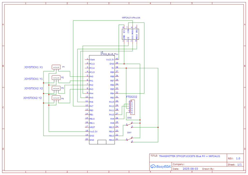
Transmitter Code
This code reads inputs from two joysticks (4 channels) and two switches (2 channels), packages the data, and transmits it via the NRF24L01 module.
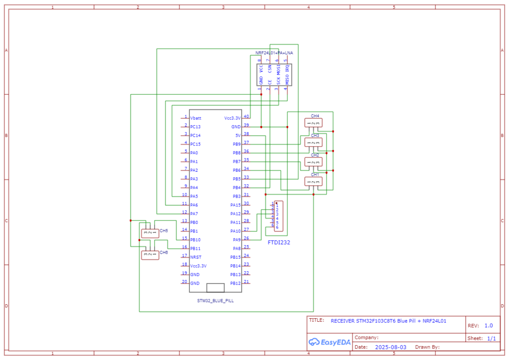
Receiver Code
This code receives the 6-channel data and outputs PWM signals to control servos or other devices. For simplicity, it maps the received data to PWM values for servos (1000-2000µs).
Leave a Reply